Software Used on this Project
Project Overview
Oasys Slope chosen for groundworks for £425 million scheme
July 2018 update: In March 2017, a Welsh politician and Economy Secretary issued a statement that detailed reports had been requested and a decision concerning £425M public funding for the race track would be available by mid-May. In June 2017 a proposed taxpayer-funded guarantee of £210million was rejected by the Welsh Government on the grounds that the financial risk was too great. Source.
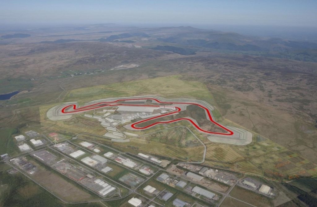
The Circuit of Wales is a proposed 6km racing circuit in South Wales capable of hosting a variety of motor sport events. The venue will also host extreme sports events, karting, motocross circuits etc. It will provide hotel and leisure facilities, a technology park and a race academy.
The design of the main circuit typically follows the profile of the existing undulating topography; however, extensive earthworks are proposed across the majority of the site to create the required finished levels for the development of the site. A key objective is to achieve an earthworks balance and reuse 2,200,000m3 of excavated material on site. The site has particularly challenging ground conditions comprising of an extensive peat bog of variable thickness overlying softened glacial clay, with these materials accounting for nearly half of the excavated material. It is proposed to reuse the peat and softened glacial till in the construction of large spectator berms which provide raised viewing areas around the main circuit. The spectator berms have a combined length of over 3km and are up to 30m in height with 1V:2H or 1V:3H slopes. Oasys Slope was used extensively in the design of the spectator berms as follows:
- Berm composition – maximising the volume of peat and softened clay used in the construction of the spectator berms.
- Berm design optimisation – optimising the design of the spectator berms for different berm heights, by zoning different materials and selective use of materials as dug.
- Slope reinforcement – design and optimisation of geosynthetic reinforcement of the steeper 1V:2H slopes.
- Basal treatment – assessing different options for leaving the peat and softened clay in-situ within the footprint of the berms.
The following sections summarise the analysis undertaken and the project savings and benefits achieved through the use of Oasys Slope.
How Oasys proved invaluable
Berm Composition
It was critical to reuse as much of the peat and softened clay as possible within the spectator berms in order to achieve an earthworks balance. Achieving an earthworks balance would result in a significant cost saving to the client and it also has many environmental benefits with the reuse of the materials that are available onsite minimising import and disposal of fill. Due to the significant volume of peat and softened clay, it was not commercially viable to improve this material with lime and/or cement to normal standards and therefore the material needed to be reused in its as dug form.
Slope was used to determine the best method to maximise the volume of peat and softened clay included in the construction of the berms with 1V:3H slopes, whilst still ensuring an adequate factor of safety was achieved. A number of different options for incorporating peat and softened clay in to the berm construction were analysed in Slope such as shoulders, layers and cores as shown in Figure 2 below.
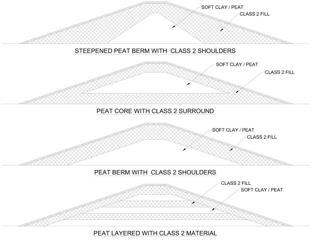
Figure 2 – Berm composition optioneering
Berm Design Optimisation
Slope was used to model both drained and undrained conditions. Drained conditions are typically critical for embankments of average height and form as shallow slips occur due to the low effective stress along the failure surface (see Figure 3). However, as the slope heights get larger, deep seated undrained failures begin to become critical. In this case, undrained conditions were found to be critical for berms over 9m high as deep slips had sufficient mass to overcome the undrained shear strength along the slip surface.

Figure 3 – Critical shallow slips in drained conditions for smaller berms (left) compared to deeper slips in undrained conditions for taller berms (right).
The earthworks will be controlled using a specification based on the Specification for Highway Work. To optimise the design for the different berm heights proposed, the introduction of subclasses of fill material allowed best use of material as dug. The glacial clay which had not been softened generally met the classification requirements for a Class 2 material. The ground investigation data indicated that the strength of the glacial clay increased with depth. As the Slope analysis had indicated that undrained conditions were critical for the taller berms, the Class 2 material was separated in to two subclasses based on undrained shear strength as indicated in Table 1. This was a more efficient use of the material available on site as the higher strength clay found at greater depth could be used for the construction of the taller bunds and placed within the parts of the berm where the critical slip circles were occurring in order to maximise its benefit.
Table 1- Subclasses of Class 2 material
| Material Type | Typical Depth Material Present Onsite | Drained Parameters | Undrained Parameters | |
| φ’ (°) | c’ (kPa) | cu (kPa) | ||
| Class 2/1 – normal strength glacial clay | 1m to 2.5m | 30 | 2 | 50 |
| Class 2/2 – higher strength glacial clay | 2.5m to 4m | 30 | 2 | 65 |
Three different berm designs were created for different slope heights as shown on Figure 4. For berms up to 9m in height, it was proposed to construct the berm from peat and softened clay with a nominal 1m shoulder of Class 2 material to provide a suitable surface for spectators to stand on. For berms between 9m and 15m in height, a thicker shoulder of Class 2 material was required for stability purposes. For berms between 15m and 23m in height, a peat and softened clay core with a surround of higher strength Class 2 material was proposed. The layer of Class 2 beneath the core was required as otherwise the critical failure surface primarily occurred through the of peat and softened clay rather than the Class 2 material as shown on Figure 5. By placing a layer of Class 2 material across the base of the berm rather than increasing the thickness of the shoulders, less Class 2 material was required to achieve an acceptable factor of safety and therefore a greater volume of peat and softened clay could be incorporated in to the berm construction.
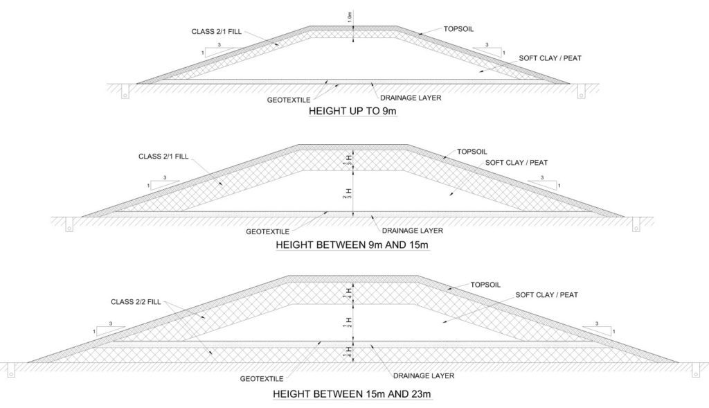
Figure 4 – Spectator berm designs incorporating peat and softened clay in their construction.
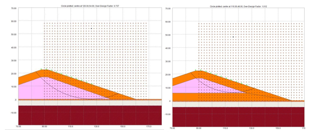
Figure 5 – Comparison of failure surfaces for berms with (right) or without (left) a layer of Class 2 beneath the core.
Slope Reinforcement
For the berms with 1V:2H side slopes, the Slope analysis indicated that it was not possible to incorporate any significant quantity of peat and softened clay in the berm construction. In addition, for the taller 1V:2H berms constructed from the higher strength Class 2/2 material alone, the stability analysis indicated that an acceptable factor of safety was not achieved. Slope was therefore used to design the required geosynthetic reinforcement (geo-grids) for berms of different heights as shown on Figure 6. The graphical output was used to target the critical slip circles and optimise the reinforcement design by modifying the geometry and tensile strength of the reinforcement accordingly. Additional flexibility was built in to the design for berms between 15m and 19m in height. Two options were provided to the contractor which used either the higher strength Class 2/2 material or higher tensile strength geosynthetic reinforcement with Class 2/1 material, depending on which options would be most cost effective or whether the higher strength Class 2/2 fill was locally available in the area of the berm construction.
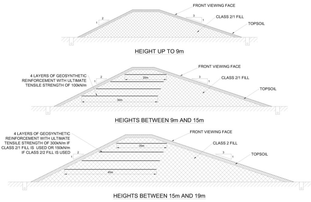
Figure 6 – Spectator berm designs with 1V:2H side slopes using geosynthetic reinforcement.
Basal Treatment
For the berms of greater height, the Slope analysis indicated that leaving the peat and softened clay in-situ beneath the berms has a significant detrimental effect on the slope stability. The Slope analysis demonstrated that for the berms over 9m in height, it was more economical to the design of the berm to excavate and replace the peat and softened clay or apply other basal treatment. Slope was used to design a number of different basal treatment options including surcharging, granular base and basal geosynthetic reinforcement as presented on Figure 7 below. These options were presented to the contractor for consideration and will be refined following further ground investigation within the footprint of the berms.
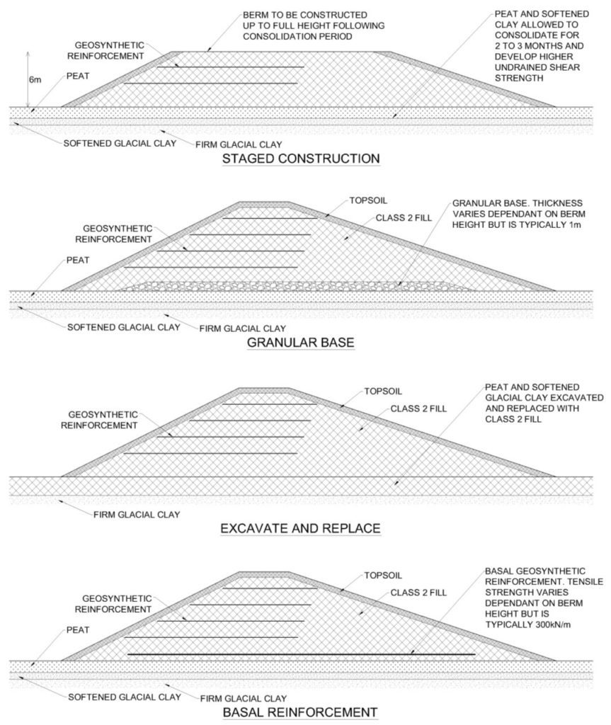
Figure 7 – Basal treatment options
Further Work
A specific element of the spectator berm design which has already been identified for further work is the geosynthetic reinforcement design. There is potential to optimise the design by using two different sets of geosynthetic reinforcement to resist the drained and undrained failures separately, which would likely result in product cost savings for the geosynthetic reinforcement. The high tensile strength geosynthetic reinforcement required to resist the deep seated undrained failures could be shortened and short lengths of lower tensile strength geosynthetic reinforcement installed near the surface of the berms to resist the shallow drained failures as illustrated in Figure 8 below.

Figure 8 – Concept geosynthetic reinforcement design to resist drained and undrained failures separately
Summary
The work presented above was undertaken as part of the preliminary scheme development. The Slope analysis demonstrated confidence in the viability of the spectator berms construction and provided a level of design certainty for project costing by the contractor. Slope was used to produce spectator berm designs which maximise the volume of peat and softened clay in the berms construction which was vital for achieving an earthworks balance, and minimising the need for offsite disposal and subsequent import of fill.
It was originally announced that an agreement has been reached to host the British MotoGP at the Circuit of Wales from 2016 and it is anticipated that detailed design for the project will commence shortly. The further development and refinement of the berm design and their site implementation will be a key element for the successful delivery of the scheme.
Acknowledgments: The author would like to thank Tim Wilkinson, Sergio Solera and Aled Phillips for their technical input and support.
