Software Used on this Project
Project Overview
St. Pancras International is a central London railway station on Euston Road in the London Borough of Camden. For a Civil Engineering bachelor’s final year individual project, the structure of the Barlow train shed at St. Pancras was assessed to discover how climate change might affect the station in the future. The main goal for this project was to better understand the stress-state of the train shed and determine whether intervention is needed at present time or in the future. Oasys GSA was used to test how different loads (resulting from climate change), would affect the structure.

Interior Barlow Train Shed
How Oasys proved invaluable
One key challenge for this project was the creation of two different models and being able to verify them accurately. Moreover, extracting values of axial, bending, shear strength as well as reactions and deflections was challenging. This was made seamless with GSA.
The first model is a single simplified arch, made up of members with the equivalent I-value of the full truss member. The arch has 19 nodes (as Barlow’s arches are made up of 18 truss sections). To obtain these values, Barlow’s drawings were imported into AutoCAD and the horizontal and vertical distances to each truss section connection were measured.
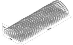
AutoCAD Isometric
To connect the nodes together, the sculpt tool was used to draw each element and the selection wizard was used to assign the wrought iron properties to the members. Before applying the increased loads from climate change to the arch, a simplified load case which was a 20kN point load just to the left of the crown of the arch was included. The results of this were then compared to the hand calculation which validated the model.
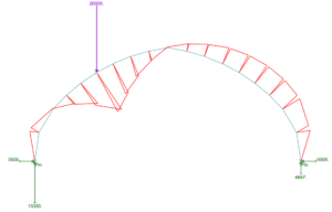
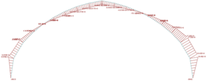
Validation, reactions and BMD in GSA
To apply the climate change load case, the ‘analyse all’ function and diagram settings were used to obtain the graphs and tabulated results.
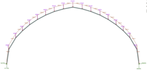
Reactions in GSA
Bending moment diagram
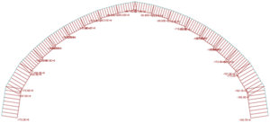
Bending stresses
Axial Stress
For the full truss model, by using the import function, the AutoCAD trussed arch as a drawing exchange file was able to be imported into GSA. The increased wind loads were then applied, and a diagram was generated for deflection.
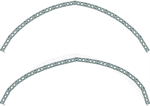
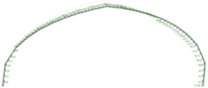
Full truss GSA model (upper) and deflection of current load case of truss (lower)
The Project Manager, Oliver Rand, explains:
“I prefer GSA as I feel it’s much more intuitive and user friendly. One thing I found particularly useful was the sculpt tool and the ability to copy and paste large lists of nodal loads, which I had to do 9 different variants of. It also helped me prove that the roof could experience double the wind load and still not fail.”
We’d like to thank Oliver for sharing this work with us.
Find out more about Oasys GSA here.

