Software Used on this Project
Project Overview
In the area of embedded retaining wall design and construction, conventional methods of restraining walls (e.g. propping, tie-back anchorage) are well established. However in recent years, engineers have had to deal with projects on which the applications of traditional propping and tie-backs are limited by site constraints. This has prompted a number of engineers to concentrate on the development and application of alternative approaches to restraining embedded retaining walls.
Overview of the Project
 The following case study is based on the paper linked below. The paper discusses two sites which both use Oasys software but this case study will focus on one of these sites, located in the Republic of Ireland.
The case study focuses on the design, construction and monitoring of contiguous pile retaining walls by Van Elle. The site constraints have led to the innovation and application of rare alternative restraint methods for the walls. Details of the design, construction and performance monitoring of the deep excavation support systems are outlined. Design predictions have been compared with monitored performance.
Proposed Developments and Constraints
The project was centred on the upgrade of a Roll on-Roll off (Ro-Ro) ramp at Dublin Port, Ireland as part of the on-going regeneration programme being embarked upon by the Dublin Docklands Authority. It was proposed to construct a new Ro-Ro floating ramp to cater for cruise liners of variable widths coming into Dublin. Van Elle Limited were appointed as the specialist geotechnical contractors for the project. The scope of the specialist geotechnical works included the design and construction of contiguous pile walls of up to 7m retained height to accommodate the proposed link span bridge, as well as heavily loaded foundation piles to support compression, tension, moment and lateral loading from the new bank seat.
All wall sections were originally required to be designed as free standing cantilevers in both temporary and permanent conditions. However, in the 6m-7m excavation area, the presence of pre-existing caisson wall bases at 11m depth rendered a cantilevered solution inapplicable and hence, this section of wall had to be provided with a form of permanent restraint. Tie-back anchors could not be used as an existing underground service culvert lies at a distance of 3m behind the wall line, while access for an anchoring rig was also a problem. Temporary propping/bracing was also not an option as working space in front of wall had to be maximised and the proposed scheme did not allow for the construction of any form of permanent restraining structure in front of wall.
How Oasys proved invaluable
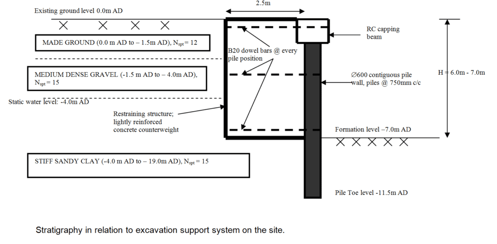
In order to overcome these constraints, an alternative solution was developed. This solution involved the simultaneous excavation of both sides of contiguous wall to 6m-7m depth and constructing a 2.5m wide concrete counterweight structure behind the wall.
The counterweight structure was built to perform two main functions;
- to provide additional gravitational support/restoring moment to contiguous pile wall;
- to provide additional stiffness/flexural rigidity to the pile wall above formation level.

Stratigraphy in relation to excavation support system on the site
Construction Sequence
Stage No. |
Description of works |
| 1 | Install Ø600 CFA bored piles @ 750mm c/c to form contiguous pile wall |
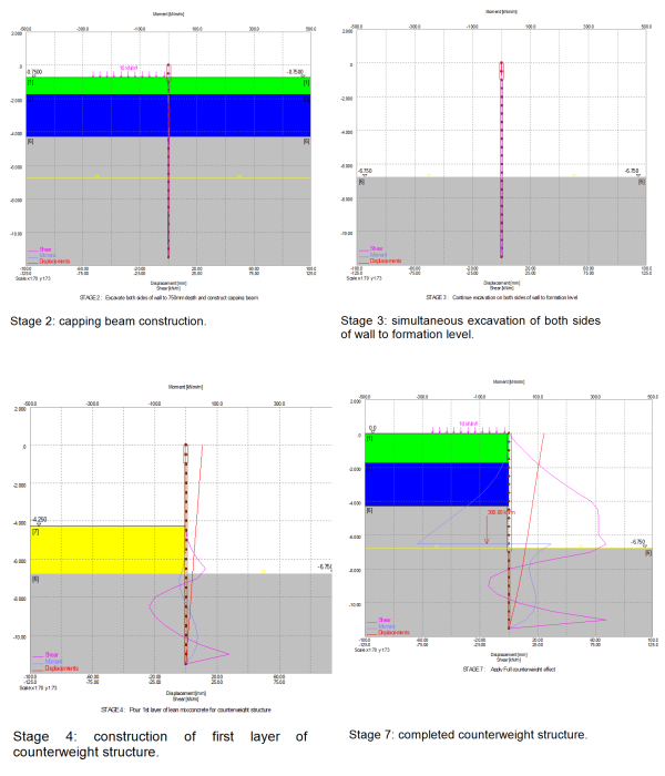
| 2 | Excavate both sides of wall to 750mm depth and construct RC capping beam (excavation behind wall only 2.5m wide) |
| 3 | Continue excavation of both sides of wall to formation level, while installing temporary shoring/formwork for counterweight structure behind wall. |
| 4 | Backfill back of wall with 1st layer of concrete (2m thickness) and dowel to contiguous pile wall. |
| 5 | After 24 hours, backfill back of wall with 2nd layer of concrete (2m thickness) and dowel to contiguous pile wall. |
| 6 | After another 24 hours, backfill back of wall with 3rd layer of concrete (2m-3m thickness) and dowel to capping beam. |
| 7 | Permanent conditions: in wall analysis, design parameters for glacial till are switched from undrained to drained, while 50% wall relaxation is also accounted for. |
Analysis
The wall on the site was designed to be restrained by a permanent counterweight structure dowelled to wall at 3 levels. Wall analysis and design involved the following;
- overall stability analysis of contiguous pile wall/counterweight structure
- serviceability analysis of contiguous pile wall/counterweight structure
- structural design of contiguous pile wall, capping beam and counterweight structure.
Overall Stability Analysis
In the overall stability analysis, an ultimate limit state approach was adopted, using factored soil parameters and loads, to estimate the required depth of embedment of the wall for overall stability.
This analysis was done with the Oasys STAWAL geotechnical limit equilibrium modelling software (now incorporated into Oasys Frew). Analysis showed the required pile length to be 11.5m, which corresponds to a minimum embedment of 4.5m below formation level.
Serviceability Analysis
In the serviceability analysis, unfactored surcharge loads and soil were used to estimate the lateral deflection of the pile wall, as well as the bending moments and shear forces on the wall. This analysis has been done with ‘Oasys FREW’ pseudo-finite element modelling software. ‘Oasys FREW’ computer output curves for lateral deflections, bending moments and shear forces at various construction stages are presented. Maximum lateral wall deflection in the temporary condition was predicted to be 22mm.

Stages in Frew
Structural Design of Contiguous Pile Wall
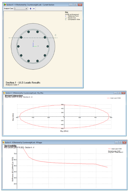
Steel reinforcements were designed to support the bending moments and shear forces estimated through the wall serviceability analysis as described above. Structural design was done to BS 8110-1: 1997 using Oasys AdSec structural modelling programme. An example cross section of the pile with associated moment interaction and serviceability plots are shown.

Steel reinforcement using AdSec
Comparison to Monitoring Data
Wall movements on the site have been monitored over periods of up to 8 months. Monitoring data have been compared with design estimates.
Both monitoring data and design predictions show the bulk of wall movement to have occurred during the construction of counterweight structure (construction stages 4-7). Approximately 60% of total wall movement occurred during these stages. This is attributable to the active thrusts mobilised behind the wall as wet concrete was being poured to form the counterweight structure.
The results also show predicted wall deflections for these stages to be higher than measured deflections; measured deflections were typically 27%-38% of estimated values. At design stage, the wet concrete had been modelled as a loose cohesionless material with effective stress parameters. However, the rapid hardening cement used may have allowed the concrete to behave as an undrained cohesive material and thus significantly reducing active pressures to values much lower than design estimates.
Construction
The construction sequence outlined in the analysis was applied on site.
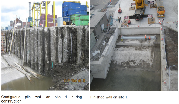
Excavation and construction of counterweight structure was followed by the construction of the permanent reinforced concrete wall in front of the contiguous pile wall, with associated drainage system. Figures show the contiguous pile wall during construction and the finished wall.
As water level was at 4m depth in the stiff sandy clay stratum, which is of low permeability, minimal groundwater control was required during excavation. Also, static groundwater level remained relatively constant during construction.

References
Novel Methods of Restraining Embedded Retaining Walls, Abid Adekunte; Pat O’ Hara, 1723, Proceedings of the 35th Annual Conference on Deep Foundations, 2010, Hollywood, CA, USA, (DFI)
Credits
Chief Engineer and Co-Author of Paper: Abid Adekunte
Geotechnical Design and Construction: Van Elle Limited
Supervising Engineers: Denanny Reidy Associates, Limerick, Ireland
Main Contractor: RAP Construction Limited, Ireland
Client: Dublin Docklands Authority
