Software Used on this Project
Project Overview
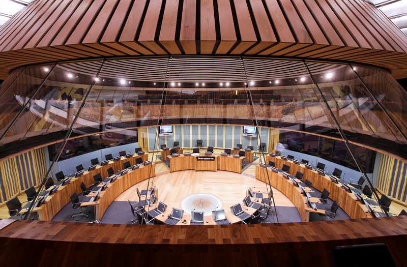
The National Assembly for Wales is a multi award winning* project located in a prominent and prestigious waterfront site in Cardiff Bay. Arup, acting as the structural engineer, worked alongside architect Richard Rogers Partnership and contractor Taylor Woodrow Construction on the project.
One of the design goals of the architects was to create a transparent floating roof by providing lateral building stability using tight, slender vertical supports. The effect was achieved by a full height glazed façade to the underside of the oversailing steel-framed roof. The internal floors are reinforced concrete. The 5,000m2 building includes a primary debating chamber, three committee rooms, offices, public space and viewing galleries.
How Oasys proved invaluable
Structural Principles
The roof geometry is formed by the intersection of six tori through a large cylinder as indicated below.

Roof geometry
There are six roof modules, five of which are typical and one that supports the bell and lantern structures. Each module is 12m by 41.5m with the end modules extending a further 2.5m on their long edge. The total plan area of the roof structure is approximately 3200m2.
The steel roof structure acts as an offset tied arch in the transverse direction. The two main arches, which span 26m, are inclined at approximately 45 degrees and have an arching ratio of approximately 1:8. The vertical thrust at the base of the arches is resisted by the primary columns and the horizontal thrust is resisted by offset ties. These ties are connected to the foot of the arches by angled struts. These angled struts also support the perimeter cantilever, which extends up to 15m at the corners of the roof. Consequently, these elements are tapered and generate a push-pull action between the main column and the side of the braced dome. The longitudinal roof members, which form the undulating roof profile, span simply from arch to arch. All the other longitudinal members are straight simply-supported beams.

Lateral stability of the roof is derived from a series of pre-stressed rods. Lateral loads on the roof are transferred to the stability members by the braced roof structure acting as a stiff diaphragm. The façade and associated structure is located 2.5m inboard from the edge of the roof structure both being structurally independent of each other. The façade loads are transferred to the stability structure by a series of props at the top of the façade mullions. The stability loads at the base of the ties are transferred to the foundations through a series of reinforced concrete shear walls.
Analysis and Design Process

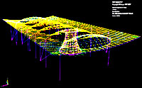
The design team initially visualized the 3D geometry in Rhino, before using this data to generate the GSA model. The resultant space frame required GSA fabric non-linear analysis, which included cable prestress, temperature and static equivalent blast loads. The results were then exported to Excel for post-processing.
