Software Used on this Project
Project Overview
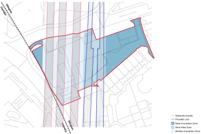
176-178 York Way is an ambitious development project located north of King’s Cross, London. It has recently received planning approval to demolish the existing buildings and construct a new structure (Use Class E) with basement levels. The project will include a Makerspace (Sui Generis) and flexible mixed-use spaces (Use Class E / Sui Generis). Additionally, the development will feature highways, landscaping, public realm works, and all associated ancillary works and structures. The building brings life to a historic brownfield site that has resisted development for over 30 years due to the presence of three shallow historic masonry railway tunnels and two deep tube tunnels that cross the irregular site from North to South. The project is the result of a close collaboration between the client, Delancey Real Estate, the architectural team, KPF, and Arup. The design team identified from inception the loading limitation imposed by the presence of the tunnels as a key site constraint critical for the design. Arup engineers significantly advanced the structural design by using Oasys GSA and the GSA-Grasshopper plugin for computational design, elevating the design to the next level.
Initial studies ruled out heroic bridging options that would span over the tunnels while maximising building height, as these would have high carbon footprints and limited piling areas, leading to significant risks. Instead, the team aimed for light building, resting on shallow foundations that could be resisted by the tunnels.
By establishing open communication between the architectural and structural teams, the team aimed to determine the optimal foundation arrangement to maximise the site’s potential for the client.
How Oasys proved invaluable
Initial analyses revealed that the shallow Network Rail masonry tunnels, just 4.5 meters below the surface, were the most limiting ones. In contrast, the deeper Piccadilly Line tunnels, made of cast iron, had a larger capacity. Contiguous buildings located over these tunnels had been limited to one or two-storey pavilions, far below the ambitions for this site, and used different foundation arrangements. To minimise the impact on the masonry tunnels, the design team aimed to ensure the tunnels behaved in pure compression, reducing any induced tension, changes in curvature, and tunnel vertical displacements.
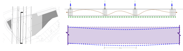
To ensure future building flexibility, the design featured long spans in the North-South direction. To avoid excessive curvature changes identified in preliminary analyses, the design team incorporated post-tension strands in the foundations. These strands work opposite to a conventional floor, transforming the column point loads into a distributed load.
Determining the optimal load distribution across the tunnels’ transverse direction was more complex. This complexity arises because the load spread and the tunnels’ resistance to the load depend on the soil stiffness and tunnel profile, making it case-specific and not generalisable.
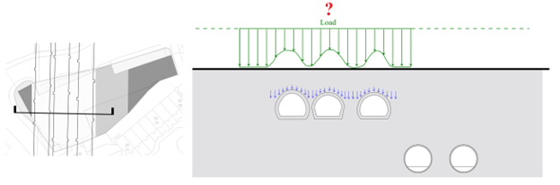
To find the answer to this question the Arup team created a Finite Element Model (FEM) of the tunnels in Oasys GSA using the GSA-Grasshopper plugin and subjected it to a Uniformly Distributed Load (UDL) that resembled what was expected to be transferred from the building.
Once the model was calibrated and verified, the team leveraged the functionality of GSA-Grasshopper, which runs GSA within the Grasshopper environment. They combined the Finite Element Model (FEM) with the multi-variable genetic algorithm optimisation solver, Galapagos, to iterate the value assigned to each individual point load. This process aimed to find the optimal solution to a predefined fitness function. The fitness function was defined as a weighted combination of variables to minimise any tension developing in the tunnels, ensuring they work in pure compression, while also minimising displacements and maximising the applied load.
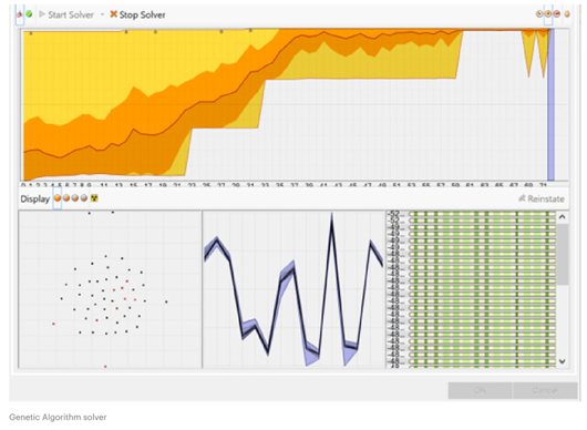
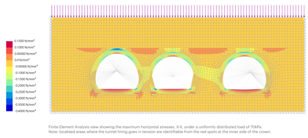
By adjusting various factors within Galapagos in combination with the simple modelling and the speed of GSA-Grasshopper, the team could easily iterate through different options and configurations to find the optimal solution. The results showed that a configuration applying the load gradually between the tunnels reduced crown tension stresses by a factor of 8, increased the applied load by 25%, and maintained the same level of displacements.
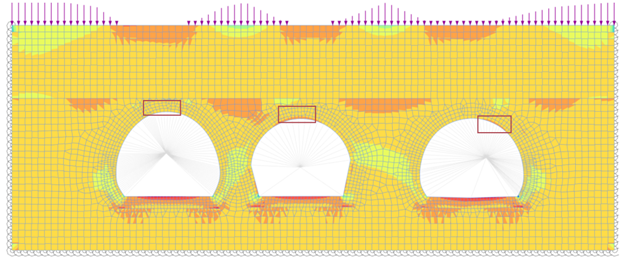
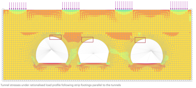
Once the ideal optimal profile was identified, it was rationalised into a series of tunnel-aligned post-tensioned strips, each 4.35 meters wide and spaced 12.5 meters apart. The results were then verified to closely match the theoretical optimum distribution, achieving a significant improvement.
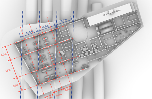
Once the optimal foundation system was identified, a clear discrepancy emerged between the optimal foundation grid (blue) and the optimal superstructure grid (red). This discrepancy arose because the foundation grid aligned with the tunnels, while the superstructure grid responded to the site geometry and user experience.
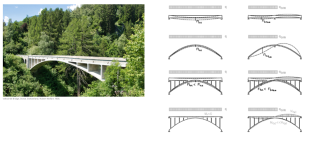
To resolve this, the design team drew inspiration from the contiguous Leslie Green Old York Road tube station’s arched gateway and Robert Maillard’s historic bridges. They proposed a series of deck-stiffened arches as a carbon-efficient system to align both grids, providing an ideal solution that respects the site’s history.
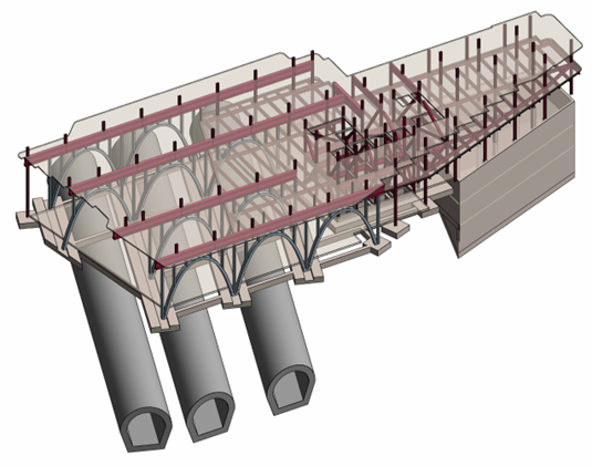
Additional uses of GSA included assessing the stiffness-dependent response of the deck-stiffened arches and checking the long-span composite floors for footfall-induced vibrations suitable for lab use.
Summary and learnings
The deck-stiffened arches celebrate the site’s constraints and the foundation solution, becoming a defining feature and identity of the building. This design perfectly combines structural solutions with architectural design intent. The project received high praise from planning officers: “It is not only a successful architectural composition but is also a remarkable feat of engineering as it spans such extensive below-ground rail-related infrastructure that was previously such a major development constraint.”
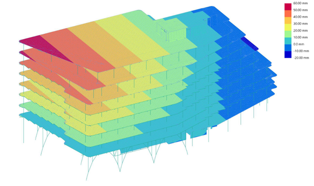
The design team further utilised GSA-Grasshopper to create the overall building finite element model, saving significant time when incorporating changes and easing model manipulation. The positive results from the GSA-Grasshopper optimisation were later verified with an advanced LS-Dyna model.
We’d like to thank Principal Structural Engineer at Arup, Miguel Martinez-Paneda for sharing this work with us.
For more information about the Oasys GSA-Grasshopper plugin, go to the GSA Docs site, get in touch with us at [email protected] or register your interest to speak directly to a member of the team.
Want to feed your curiosities right away? Watch our webinar covering the endless possibilities of GSA-Grasshopper.
Photo credit: KPF