Software Used on this Project
Project Overview
The Wheatley Park embankment is a 4.5km-long earth embankment situated on the right bank of the River Don. This flood embankment, along with the access track and foreshore, is separated by a narrow strip of land between the river to the north and the South Yorkshire Navigation Canal to the south. Bank instability is currently affecting both the access track and the flood embankment, posing a risk of breach that could potentially impact 700 properties. Previous interventions to address these issues have included the installation of sheet piles, rock bags, rock armour, and slope re-profiling. Arup was appointed to manage the project and, early on, recognised the importance of establishing a BIM Execution Plan (BEP) to streamline the design process. Utilising Oasys Slope and Grasshopper 3D, the engineers conducted comprehensive slope stability analyses to determine high risk areas where works were needed.
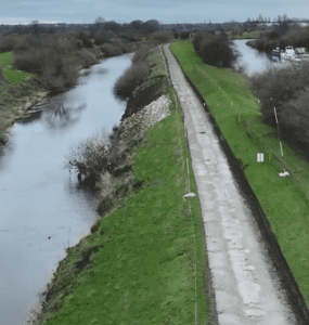
Wheatley Park embankment between the River Don (left) and canal (right)
How Oasys proved invaluable
To successfully apply digital innovation to the Wheatley Park Embankment project in Doncaster, a BEP was developed at the outset using a Location Strategy to guide the design process. The BEP enabled the design team to divide the 4.5km flood embankment into 11 manageable assets, aligning with Environment Agency asset referencing. LiDAR and photogrammetry data were received based on the BEP, facilitating easier data manipulation and the development of 3D models.
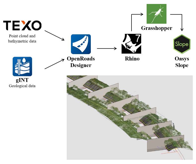
Workflow and point cloud data displayed in OpenRoads Designer with sections generated at 20m intervals
Drawing on lessons from other infrastructure projects with long linear assets, such as highways and railways, the design team pioneered a method to integrate slope stability analysis with OpenRoads Designer, automating the process efficiently.
Point cloud data from the LiDAR and bathymetry surveys were imported into OpenRoads to create a 3D model, allowing sections to be cut at any given point—230 sections were cut at 20m intervals. gINT was used to assess ground conditions and produce sections at identical intervals featuring borehole sticks. The gINT data was then overlaid into OpenRoads to combine the slope geometry and geology to allow selection of critical sections for stability analysis.
Once the critical sections were identified, Rhino CAD software was employed to manually draw the ground strata—the only manual operation in the process. Grasshopper 3D was then used to import the sections directly into Slope to test multiple slope runs.
Over 100 slope runs were undertaken at various locations along the embankment with both existing and proposed geometry. This workflow allowed these slope runs to be generated much more efficiently.
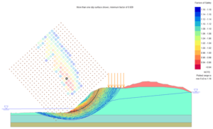
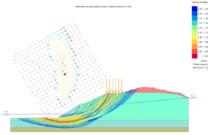
Oasys Slope runs for a critical section, showing existing geometry (left) and proposed solution with slope regrading and rock armour (right)
This approach provided an efficient and robust method to identify high-risk areas, focusing the design efforts where they were most needed.
We’d like to thank Associate, Gerard Studds and Geotechnical Engineer, Callum Thorpe at Arup for sharing this work with us.
Learn more about Oasys Slope.