Software Used on this Project
Project Overview
Using live willow as a material for slope and river bank stabilisation is both sustainable and environmentally friendly. However, willow spiling has received little technical analysis , so there is no published data on the design parameters required for the system or how the system reacts under load. Hence it has been difficult to predict the likely displacements, which means it has only been used in situations where ground movements aren’t an issue.
How Oasys proved invaluable
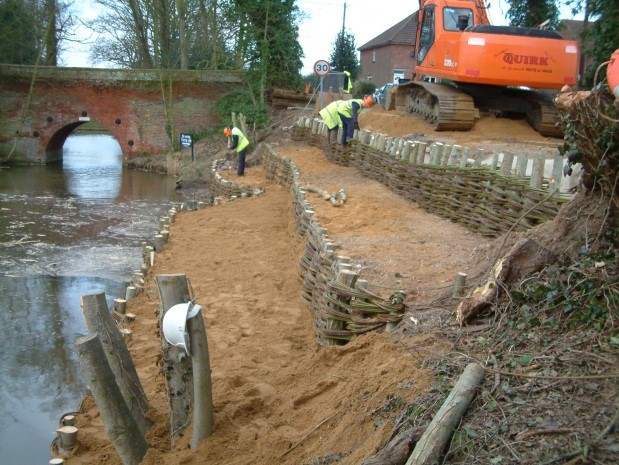
A site in Norfolk during installation
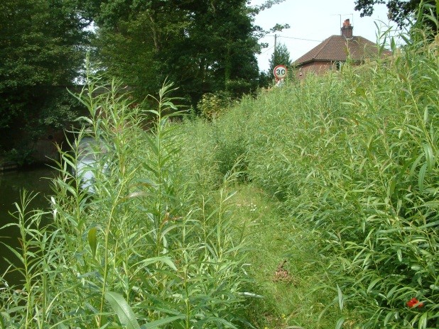
and 6 months later
The aim of the project was to measure the horizontal displacements of newly installed willow spiling, tested under progressively increasing loads.
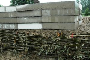
The spiling comprises willows with live posts, 100mm in diameter and installed at 0.6m centres. Willow withies are woven horizontally between the posts to retain the ground behind. Retained heights of 600mm, 800mm and 900mm high were used in the trials. All retained heights were subjected to the same loading regime, and backfilled with the same material to the same earthworks specification. Photographs of the load being applied to the spiling presented below:

Software usage
Oasys Frew Version 19.0 compared the predicted and measured displacements to produce design parameters for various loading situations.
Frew allowed a variety of scenarios to be modelled to show the influence of wall friction and the stiffness of the “wall” on the displacements. These results were compared to those from the field trials.
Initially a surcharge of 5kN/m² was applied. When this situation was modelled in Oasys Frew, only the stiffness of the posts (EI = 72kNm²/m run) was included in the first calculation. The friction on the back of the wall i.e. δ/Ø’, was varied between 0 and 1.0 in order to investigate the effect of friction on the calculation of displacement. The output is summarised in the table below:
| OASYS FREW | FIELD TESTS | |||
| Wall Friction δ/Φ | Max disp (mm) | Min disp (mm) | Max disp (mm) | Ave disp (mm) |
| 0 | 6.36 | 2.75 | 8.5 | 5.25 |
| 0.66 | 3.96 | 2.75 | 8.5 | 5.25 |
| 1.0 | 3.35 | 2.75 | 8.5 | 5.25 |
A comparison of the model and field results shows there is little wall friction between the soil and the posts during the initial loading of the spiling – only the posts are acting initially to restrain the soil and the surcharge. While this result is consistent between the model and the field test, using standard design techniques may underestimate the displacements locally due to the variability of the natural materials used and the contact achieved between the soil and the posts. From the results above it can be seen that if no wall friction is assumed i.e. the contact between the soil and the posts is poor, the deflections calculated are around 3mm greater than when the contact is good i.e. wall friction is equal to 1.0. When no wall friction is present the calculated results correspond closer to the maximum deflections measured and where the wall friction is equal to 1.0, the calculated deflections correspond more closely to the minimum deflections recorded.
When the 10kN/m² and 15kN/m² surcharges were applied they did not produce significant increases in the displacements in the field. When using a wall friction ratio of 0, a displacement of 16.10mm was calculated, compared to an average value of 3.88mm measured in the field. It became apparent during the back analysis that a transition zone was identified over these loads caused by one or a combination of the following factors:
- Ground compression during loading, pushing it forward onto the back of the spiling causing the soil to interlock with the spiling and increasing the wall friction,
- As the surcharge was applied the made ground became more dense and therefore the angle of internal friction and the Youngs Modulus increased,
- As the ground behind compressed and moved forward, the spiling was ‘tightening up’, hence acting as a waler and transferring load onto the posts.
With the wall friction ratio increased to 0.66 and 1.0, but with no contribution from the stiffness of the spiling or an increase in the soil consistency, displacements of 10.4mm and 9.1mm respectively were recorded. While the displacement of 9.1mm coincides well with the maximum displacement, it overestimates the average displacement of 3.88mm considerably.
The 15kN/m² surcharge was considered using a wall friction value of 1.0 and the original soil parameters. Displacements of 17mm were calculated, exceeding the maximum recorded displacement in the field by around 7mm. Therefore it was concluded that at this surcharge some improvement of the ground was occurring, so the soil parameters were amended to:
- bulk density of the made ground was increased to 19kN/m²,
- angle of internal friction increased to 40°
- Youngs Modulus increased to 45,000kN/m².
Using the improved soil parameters and a wall friction of 0.66 along with only the stiffness of the posts, Oasys Frew calculated displacements of 4.48mm, which compares well with the average displacement of 5.12mm.
At the 20kN/m² surcharge it appeared the final stage of the transition occurred during which the spiling tightened up and acted as a waler.
When the timber spiling is constructed, the withies are wrapped by hand around the timber posts, but as the soil behind compacts, it moves forward onto the back of the spiling and the withies to tension up. As the tension increases the spiling will start to act as a beam and the rigidity of the overall system will increase.
The withies only can be considered to be acting as a beam 100mm deep and 600mm wide between the posts giving a (EI) of 440kNm²/m run. Alternatively the stiffness could be calculated for an average of 200mm thick spiling i.e. 100mm diameter posts and 50mm thick spiling (passing both sides of the post), resulting in an EI value of 3520kNm²/m run.
The wall friction will be applied to both the back of the spiling i.e. GL to 0.6m, and the posts i.e. 0.6m to 2.0m. The stiffness of the posts remained as 72kNm²/mrun below ground level.
The results are summarised below:
| FIELD RESULTS | OASYS FREW | |||
| Min/Max disp (mm) | Average disp (mm) | Wall friction δ/φ | EI (kNmm2) | Max disp (mm) |
| 5.5 / 12 | 7.75 | 0.66 | 440 | 6.77 |
| 5.5 / 12 | 7.75 | 1.0 | 440 | 5.5 |
| 5.5 / 12 | 7.75 | 0.66 | 3520 | 6.74 |
| 5.5 / 12 | 7.75 | 1.0 | 3520 | 5.48 |
The calculated results using a wall friction ratio of 1.0 model the minimum displacements very closely, confirming that a good contact between the soil and the spiling is significant for controlling displacements. The spiling thickness does not have a significant effect on the displacements, probably due to the majority of the deflection being controlled by the bending generated in the posts just below the excavation level.
The 30kN/m² surcharge was modelled using the same soil parameters as in the 20kN/m² surcharge but will the lower bound spiling stiffness of 440kNm²/m run. The results are presented below.
| OASYS FREW | FIELD TESTS | |||
| Wall friction δ/φ | Max disp (mm) | Min disp (mm) | Max disp (mm) | Ave disp (mm) |
| 0 | 25.5 | 20.5 | 31.5 | 24.3 |
| 0.66 | 13.7 | 20.5 | 31.5 | 24.3 |
The average calculated values and the field results correlate quite closely when the wall friction is reduced back to zero i.e no friction. When wall friction is present the displacements are underestimated by around 7mm.
The likely reason for the reduction in wall friction is that the settlement of the soil behind the wall will generate negative skin friction, which is equivalent to a vertical load acting on the timber piles. Since the timber piles are only 150mm in diameter and 2.0m long, their ultimate skin friction capacity is around 5kN. The negative skin friction generated by the surcharge alone is in the region of 9kN, so some downward movement of the piles is likely to have occurred. Vertical movement was not measured during the field trial to collaborate this theory. The downward movement of the timber posts would negate any wall friction acting on either the posts or the spiling.
The 40kN/m² surcharge was modelled using the same parameters i.e no wall friction and improved soil parameters. OASYS FREW calculated a displacement of 49.9mm and field tests recorded an average displacement of 51.2mm. At this load the withies were seen to be starting to break and showing signs of failure, i.e. starting to reach its ultimate capacity.
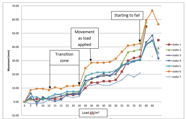
The zones through which the willow spiling passes during loading are shown below:
The aim of this project was to increase confidence in bioengineering techniques as an environmentally friendly option for slope stabilisation solutions. The intention was to produce design parameters for the spiling under various loading situations and for various heights of terraces. Until further research is undertaken, the following design parameters could be used:
| Surcharge (kN/m²) | Consistency of backfill | Wall friction (δ/Φ) | Comments |
| 5 | Loose | 0 | Average displacements slightly over estimated. If wall friction increased to 1.0, minimum displacements calculated quite closely. |
| 10 | Loose | 1.0 | Maximum displacement calculated, but since common surcharge for paths, pavements and roads, then calculating maximum displacement is reasonable. |
| 15 | Dense | 0.66 | Determines average displacement well, if supporting sensitive structures/ services/ surfacing, then wall friction should be reduced |
| 20 | Dense | 0.66 | Determines average values well, if supporting sensitive structures/ services/ surfacing, then wall friction should be reduced |
| 30 | Dense | 0 | Vertical load overcoming wall friction |
| 40 | Dense | 0 | Failure occuring |
Further monitoring of constructed spiling will be done to improve confidence that the willow spiling system can be used in more sensitive situations where loadings and displacements are critical.